01 — THE DATA-CENTRE-PLUS-STORAGE CASE
Data centre demand has decoupled from grid build-out timelines. AI compute, hyperscale expansion, and the migration off legacy UPS architecture converge on one point — the operator now needs storage to make the project bankable, not just resilient.
Grid interconnection delay is the dominant project blocker. Major TSOs across Frankfurt (Amprion / TenneT), Dublin (EirGrid), Amsterdam (TenneT NL), and London (National Grid ESO) face MV/HV connection queues of 3–7 years for new data centre loads above 50 MW, depending on zone and feeder capacity — figures aggregated across published TSO connection-queue disclosures and Ember’s June 2025 grid-for-data-centres analysis. The connection itself isn’t the issue — it’s the upstream substation and transmission build that gates the date. Battery storage at the site lets the operator go live on a constrained import contract, then scale as the grid catches up. The BESS bridges the gap between commissioning and full-grid availability without forcing the operator to commit diesel-UPS capex twice.
Diesel UPS replacement is regulatory pressure now, not just sustainability ambition. EU Taxonomy disclosure and CSRD reporting both require scope-1 emissions accounting for backup-generation diesel use. Major hyperscalers have signed climate-neutrality commitments tied to 2030. Lithium-iron-phosphate UPS replaces 30-second diesel start-up cycles with sub-second response, removes the on-site fuel inventory, and converts a scope-1 line item into a scope-2 grid draw covered by the operator’s PPA stack.
AI training spikes have overrun legacy UPS dynamic response. Modern GPU clusters ramp from idle to nameplate within seconds, then drop again as workloads complete. Traditional flywheel and battery-string UPS architectures were sized for an outage event, not repeated multi-MW load swings during normal operation. Grid-forming BESS at data-hall scale absorbs the swings without dragging on the grid feeder or triggering downstream voltage events that propagate into the dual-cord IT load.
02 — WHAT THE BATTERY DOES


03 — INTEGRATION ARCHITECTURE
Mode A
Mode B
Mode C
04 — SIZING LOGIC
Lever 01
Lever 02
Lever 03
Rule of thumb
20 MW data centre on a 10 MW import contract: typically a 10 MW / 20–40 MWh BESS for a 2–4 hour bridge duration. 100 MW hyperscale campus on phased interconnection: typically 30–60 MW / 60–180 MWh distributed across multiple containers. These are starting points for feasibility, not engineering numbers — actual sizing factors in the operator’s RTO/RPO targets, the AI compute mix, the cooling load profile, and the TSO interconnection schedule.
05 — RECOMMENDED HENLEY PLATFORM
06 — REFERENCE PROJECTS
Note from engineering
Henley Power’s deployed portfolio to date is dominated by utility solar-plus-storage and PV-storage-diesel hybrids — Inner Mongolia, Ningxia, Hebei, Henan, Shandong provinces in China, plus a Sahel-region microgrid in Chad. Data-centre-specific commissioned reference projects are in development with European colocation operators.
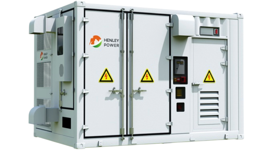
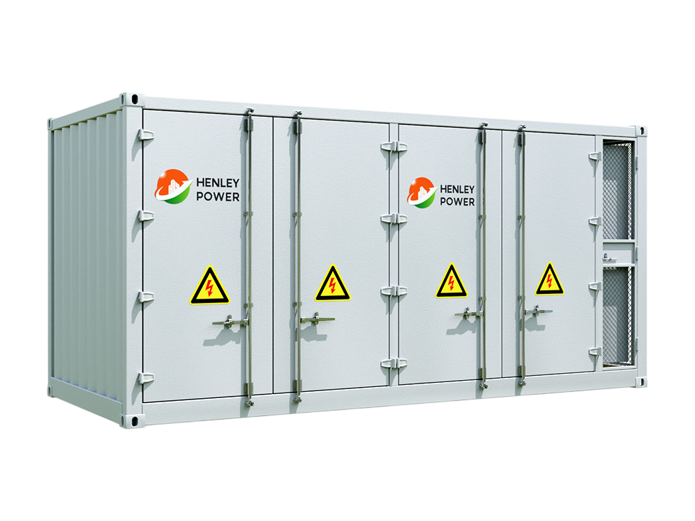
The technical reality is that the BESS platform — 2 MWh and 5 MWh containerized blocks today, 3 MWh and 4 MWh as project-spec configurations — is application-agnostic at the container and PCS level. The engineering differences between utility solar pairing and data-centre integration live in the control logic, the protection coordination with the dual-cord IT load, and the SLA structure — not in the cell architecture or the cabinet. Pre-commissioning data-centre references and engineering studies are shared after NDA on request, and our deployed utility portfolio is the closest analogue at the platform level.
If your project needs a fully data-centre-deployed reference site as a pre-condition to specification, we’ll say so openly rather than over-promise. Browse current project portfolio →
07 — FAQ
09 — RELATED SOLUTIONS